En stock Producto destacado
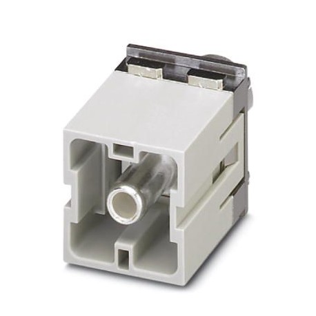
HC-M-HS 200/70-MOD-ST-PE
HC-M-HS 200/70-MOD-ST-PE 1636907 PHOENIX CONTACT Contact insert module
$0.00USD
4468 en stock
Especificaciones clave
GTIN:4046356095211
Nota:Made to Order (non-returnable)
Clave de pedido:1636907
Página del catálogo:Page 551 (C-4-2015)
Información del proveedor
Productos: 0
Normalmente se envía dentro de 2-3 días hábiles
Calidad garantizada
Envío rápido
Soporte técnico
Especificaciones técnicas
| Parámetro | Valor |
|---|---|
| GTIN | 4046356095211 |
| Nota | Made to Order (non-returnable) |
| Clave de pedido | 1636907 |
| Página del catálogo | Page 551 (C-4-2015) |
| Unidad de embalaje | 1 pc |
| País natal | DE (Germany) |
| Número de arancel aduanero | 85366990 |
| (Condiciones ambientales) | 16 mm (70 mm²) |
| Material de contacto (General) | Copper alloy |
| Corriente nominal (Dimensiones) | 200 A |
| Ancho (Datos Comerciales Clave) | 34.2 mm |
| Altura (Datos Comerciales Clave) | 54.5 mm |
| Longitud (Datos Comerciales Clave) | 29.4 mm |
| Perfil de conexión (Dimensiones) | PE |
| Material portador de contactos (General) | PC |
| Material de la superficie de contacto (General) | Ag |
| Serie (Características mecánicas) | HC-M-HS |
| Peso por pieza (sin embalaje) | 97.600 g |
| Hexágono interior (Condiciones ambientales) | WAF 5 |
| Par de apriete (condiciones ambientales) | 9 Nm (40 - 50 mm²) |
| Conexión (Características mecánicas) | Note on axial connection technology:Only for stranded wires. The specified conductor cross sections refer to the geometric cross section of the cable used.Use of cables with a geometric cross section that differs greatly from the nominal cross section of the cable should be checked before use.The wiring space for axial screw technology is designed for fine strand cables according to VDE 0295 Class 5. Deviating cable structures (e.g., Class 6 cables) should be checked before use.Assembly instructionsBefore assembly, ensure that the tapered screw is turned back all the way (chamber is open). The cables must not be twisted. The wires should be inserted as far as they will go into the contact chamber (until the insulation touches the contact). Hold the wires in position and use the socket wrench to tighten. The used wire end should be cut off before connecting again. The connection screw may only be retightened once to prevent the litz wires from breaking. To prevent damage to the contact, the wire/cable should be mechanically intercepted at an appropriate distance from the connection point (e.g., by using a plate cutout). DIN VDE 0100-520:2003-06 contains information on how to do this correctly. The module cannot be used simultaneously with HC-B..-TMB-SD-IP65 and HC-B..-TMS-SD-IP65 protective covers.PE mounting plateThe PE plate must be pressed hard against the swing frame using the 4 screws. First loosen the 4 screws of the PE plate and then tighten them again once the module is fixed in the swing frame. |
| Altura mínima de la carcasa (Condiciones ambientales) | 72 mm |
| Sección transversal del conductor (condiciones ambientales) | 40 mm² ... 70 mm² (The cross section specification refers to the geometric cross section of the cable used) |
| Método de conexión (Características mecánicas) | Axial screw connection |
| Conexión según norma (datos del material) | UL |
| Ciclos de inserción/extracción (Condiciones ambientales) | ≥ 500 |
| Sección transversal de conexión AWG (Condiciones ambientales) | 1 ... 00 |
| Instrucciones de montaje (Características mecánicas) | - Use only flexible conductors,- Connection of wires with 5 mm an Allen wrench,- Housing height h ≥ 72 mm,- Connectors may only be operated without load/voltage. |
| Número de ranuras para módulos (Características mecánicas) | 2 |
| Clasificación de inflamabilidad según UL 94 (datos del material) | V0 |
| Diámetro del cable incluido el aislamiento (condiciones ambientales) | 12 mm (40 mm²) |
| Temperatura ambiente (funcionamiento) (Características eléctricas) | -40 °C ... 125 °C |
| Longitud de pelado de cada cable (condiciones ambientales) | 16 mm |
| Clasificación de inflamabilidad según UL 94 (Características mecánicas) | V0 |
Descripción del producto
More details
Características clave
- Calidad de grado industrial
- Cumple con RoHS
- Certificado CE
- Garantía de 1 año
Documentos del producto
Hoja de datos
Especificaciones técnicas y datos de rendimiento
Manual de usuario
Guía de instalación y operación


